Assets are licensed under: https://dpel.aswf.io/alab/alab-license/
]]>
Assets are licensed under: https://dpel.aswf.io/alab/alab-license/
]]>The Moana island data set uses Ptex, which stores textures per face instead of per-mesh. This parameterization removes the need for per vertex uv’s, and removes the need for artists to painstakingly create UV maps. However, it also means that a custom filtering and streaming system will be needed. The total texture footprint is 28 GB, which exceeds the memory capacity of my GPU, so a fast, Ptex-native streaming system is necessary for interactive rendering.
Luckily, Disney recently gave a talk at SIGGRAPH about this exact problem [Lee et. al. 2025]. My system closely follows this paper, with some modifications since I’m using Vulkan instead of CUDA.
Every frame, the renderer writes the ptex face ID, texture ID, and mip level requested by all camera primary ray hits, and stores them to a feedback buffer.
This feedback buffer is copied from device to host memory, and then copied to a ring buffer. On separate threads, feedback requests are read from this ring buffer, duplicate requests are pruned,
and unmapped requests are loaded from disk. The loaded textures are allocated using a GPU slab allocator with 512 KB chunks. These chunks can only allocate textures with fixed dimensions,
such as 128x128 or 32x64. All textures are rotated so that their width is greater than their height, which reduces the number of unique slabs. A Texture2DArray is used for each slab,
which allows the worker threads to asynchronously transition image layouts and synchronize each individual array layer. Every layer of every texture array is individually accessible on the GPU
using bindless descriptors, significantly simplifying descriptor management. At runtime, a hash table is used to map the face ID, texture ID, and mip level to this bindless descriptor,
allowing the entire texture cache to be easily accessed. If there is no hash table entry, a 1x1 fallback is used.
One issue with the above system is that texture memory is usually aligned to a power of two value, such as 512 or 1024 bytes. This alignment applies to each indiviudal layer of a texture array, not to the whole array, which means that slabs with 1x1 or 2x2 textures would waste a significant amount of memory just on alignment. Thus, the minimum width and height of a texture array is limited to 16, and textures with dimensions smaller than this are packed into mini 16x16 atlases within a particular array layer. Since these small textures no longer occupy an independent layer of a texture, they must be synchronously uploaded to the GPU.
For primary ray hits, it’s possible that many threads in the same warp will intersect the same face. To reduce the number of duplicate requests, I’ve implemented a fast per-wave compaction scheme using WaveMatch (see here). This intrinsic returns a bitmask that represents the set of lanes with a value matching the one in the current lane. When multiple threads in a wave have an identical feedback request, only the thread with the highest index will write the request to the feedback buffer, which prunes duplicate requests.
uint2 feedbackRequest = uint2(textureIndex | (tileIndex << 16u), faceID | (mipLevel << 28u));
uint4 mask = WaveMatch(feedbackRequest.x);
int4 highLanes = (int4)(firstbithigh(mask) | uint4(0, 0x20, 0x40, 0x60));
uint highLane = (uint)max(max(highLanes.x, highLanes.y), max(highLanes.z, highLanes.w));
bool isHighLane = all(feedbackRequest != ~0u) && WaveGetLaneIndex() == highLane;

// only the highest index thread for each identical set increments the atomic counter
uint index;
WaveInterlockedAddScalarTest(feedbackBuffer[0], isHighLane, 2, index);
if (isHighLane)
{
    // write request
    feedbackBuffer[index + 1] = feedbackRequest.x;
    feedbackBuffer[index + 2] = feedbackRequest.y;
}
Texture filtering is the same as in the above talk. To give a brief overview, instead of taking multiple taps per texture request, applying weights to each tap, and then summing up the contributions (traditional filtering), the weights of the filter are used as a PDF that is sampled once with nearest-neighbor. This removes the need for texture borders, which are commonly required in texture streaming system. For more details, see the above talk and this paper.
Originally, I attempted to implement a hierarchical LOD streaming system, heavily inspired by the recent Zorah demo from NVIDIA. I ended up removing this system and simply storing all of the BLASes in GPU memory, with no streaming.
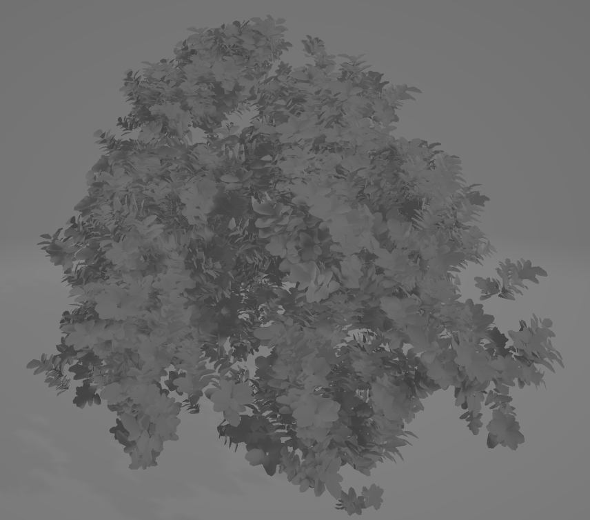
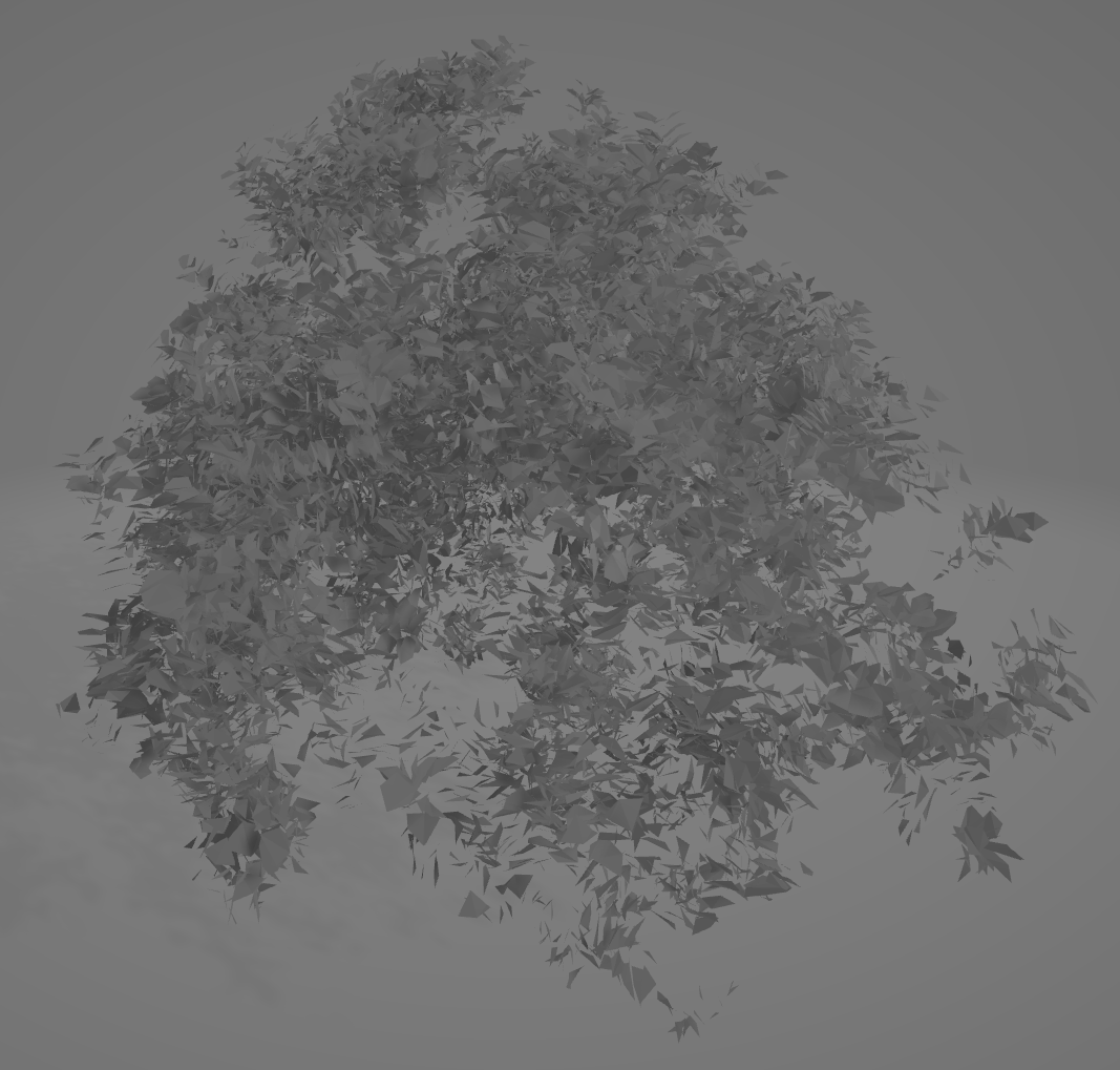
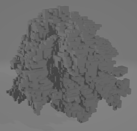
One issue with the LOD system was due to a commonly known problem with quadric error mesh simplification (QEM), which is used when generating cluster LODs. QEM struggles when geometry contains a large number of unconnected islands, which is very common in foliage. Below are some images demonstrating the problem.
Recent work from Epic Games addresses this issue with Nanite Voxels, first introduced in the Witcher 4 demo. Instead of simplifying clusters with QEM,
clusters are first voxelized, with a voxel size matching the error returned by the quadric error process. If the number of voxels returned from the voxelization process is above some threshold,
the process is repeated with a larger voxel size until the threshold is met. If the final voxel size is still less than the QEM error metric, then then voxelized version
of the cluster is used for all future simplification steps. The voxelization process follows the method outlined in Hybrid mesh-volume LoDs for all-scale pre-filtering of complex 3D assets
[Loubet and Neyret, 2017]. First, voxels are generated from a cluster using traditional methods. Afterwards, for each voxel, a ray is randomly generated within a small disk
centered at the center of the voxel. The ray is bounded such that its tMax is at the voxel’s boundary, and then traced against the original, unsimplified mesh. If the ray intersects geometry,
the normal of the intersected geometry is added to an SGGX normal distribution. The code for the offline voxelization process is at Engine/Source/Developer/NaniteBuilder/Private/Cluster.cpp.
This system was designed for rasterization, so I attempted to implement a version of it that would work with ray-tracing. Below is an image of a voxelized foliage element.
In the end, I couldn’t get the appearance of the voxels to quite match the original geometry. I originally tried to implement this system because I thought it would be necessary, but I realized after I implemented it that the base unique geometry could fit in GPU memory with no streaming. Also, it was unclear how to handle the texture parameterization of the simplified clusters (both triangles and voxels). The QEM simplification process assumes that the input mesh has a single texture parameterization, which conflicts with the Ptex representation. Converting from Ptex to traditional uv’s would’ve been a pretty significant undertaking that I’m glad I did not have to do.
Outside of the obvious lack of curves, the culling of sub pixel instances mentioned in the previous post is currently not strict enough at certain camera viewpoints. This means that some instances are not rendered when they should be. For the texture streaming system, there are magnification artifacts at close view distances, which is a known limitation with the above filtering method. Research regarding solutions for this problem have been published, but have not been implemented.
Thanks for reading this far! If you have any questions regarding anything, feel free to send an email.
Lee et. al 2025, “A Texture Streaming Pipeline for Real-Time GPU Tracing” https://www.yiningkarlli.com/projects/gpuptex.html
Loubet and Neyret 2017, “Hybrid mesh-volume LoDs for all-scale pre-filtering of complex 3D assets” https://hal.science/hal-01468817
Pharr et. al 2024, “Filtering After Shading With Stochastic Texture Filtering” https://dl.acm.org/doi/10.1145/3651293
Ptex https://ptex.us/
The SGGX microflake dstribution https://dl.acm.org/doi/10.1145/2766988
WaveMatch https://microsoft.github.io/DirectX-Specs/d3d/HLSL_ShaderModel6_5.html#wavematch-function
Witcher 4 Demo https://www.youtube.com/watch?v=Nthv4xF_zHU
Zorah https://www.nvidia.com/en-us/on-demand/session/gdc25-gdc1002/
]]>Acceleration structures (AS) are ubiquitously used in ray-tracing applications in order to reduce the number of ray-primitive intersection tests. There are multiple types of acceleration structures, such as kd-trees, grids, and bounding volume hierarchies (BVHs). The rest of this post will focus on BVHs since they are the standard data structure used in hardware ray tracing implementations. BVHs are a tree hierarchy of bounding volumes (boxes or spheres), where each bounding volume represents the total volume of a collection of primitives. In such a hierarchy, the root node represents the whole scene, and child nodes contain a subset of the primitives in the parent node. This structure reduces the complexity of ray tracing from O(N) to O(logN), and allows for quick rejection of an aggregate of primitives if their bounding volume is not intersected by a ray.
Graphics APIs, such as Vulkan and Direct 3D 12, provide function calls that can be used to build acceleration structures over a collection of triangles or AABBs, called a bottom level acceleration structure (BLAS). These BLASes can be used to build a top level acceleration structure (TLAS), which comtains instances of multiple BLASes. Once TLASes are built, they can be accessed in GPU shaders, significantly speeding up ray tracing operations compared to CPU implementations. However, there are several issues with these ray tracing APIs. Acceleration structures can take up a significant amount of VRAM, which eats away at the limited memory budget on consumer GPUs (8-16 GB). These acceleration structures also can be slow to build on the GPU, especially when dealing with millions of primitives. While slow build times aren’t as much of an issue for static geometry, they can have a significant impact on frame times in scenes with dynamic geometry, such as skinned meshes. To combat these issues, developers have either had to reduce the number of primitives in these acceleration structures by using simplified versions of scene geometry, or reduce the frequency of builds. For example, in Remedy Entertainment’s Alan Wake 2, the frequency of AS updates decreases based on the view distance of an object from the camera [Kandar et. al. 2024]. Both of these solutions lead to geometry in the AS no longer matching the directly visible geometry, leading to self-intersection artifacts.
To address these issues, NVIDIA recently released the RTX Mega Geometry API, which introduces new types of acceleration structures. Instead of building a traditional bottom level acceleration structure (BLAS) over triangles, BLASes can now be built over cluster level acceleration structures (CLAS). These CLASes can only be built over a few triangles and vertices (usually < 256). CLASes are well suited for hierarchical cluster level of detail (LOD) systems, such as Nanite. Instead of having to rebuild an entire mesh’s BLAS when the LOD of only a few clusters changes, only the new clusters’ CLAS have to be built. The BLAS build over clusters is also significantly faster, since there are ~100x less clusters than triangles. There also now exists a cluster template acceleration structure, which takes an index buffer and precomputes information used in the AS that is independent of position. These templates can then be instantiated with vertex data, speeding up build times. This type of acceleration structure is well suited for both dynamic and tessellated geometry.
Although the primary benefit of this new API is reduced build times, it turns out that these new acceleration structures consume less memory compared to traditional triangle BLASes. Below is a table showing a comparison in AS memory footprint between a traditional triangle BLAS and clustered acceleration structures. The CLAS total acceleration structure size includes all individual CLAS, as well as the cluster BLAS. The traditional triangle BLAS size is after compaction.
| Filename | Vertices | Triangles | CLAS Total Accel Size (in KB) | Triangle BLAS Total Size (in KB) |
|---|---|---|---|---|
| isMountainB/archives/xgBreadFruit_archiveBreadFruitBaked.obj | 3,070,229 | 4,216,610 | 49,226 | 105,706 |
| isIronwoodA1/isIronwoodA1.obj | 23,226,138 | 39,083,858 | 422,890 | 808,734 |
| isCoral/archives/xgFlutes_flutes.geo | 55 | 318 | 1.25 | 3.375 |
| isCoral/isCoral.obj | 1,877,141 | 2,894,788 | 33,077 | 75,408 |
| isPalmRig/isPalmRig2.obj | 84,422 | 132,320 | 1,537 | 3,235 |
| isBeach/isBeach.obj | 36,781 | 55,836 | 692 | 1,383 |
| isMountainA/isMountainA.obj | 43,890 | 67,006 | 924 | 1,776 |
| isDunesA/archives/xgHibiscusFlower_archiveHibiscusFlower0009_mod.obj | 2,428 | 3,888 | 44 | 98 |
Using CLAS saves roughly 50% per unique mesh, with the savings being larger for some meshes. For the Moana island scene, the total amount of AS memory saved is 1549 MB.
One caveat regarding these build sizes is that they are computed on the GPU, not the CPU. The Vulkan API provides a CPU function that returns an estimate
of the memory required by a CLAS or cluster BLAS, named vkGetClusterAccelerationStructureBuildSizesNV (spec).
This function returns a worst case memory amount, given the specified maximum number of triangles and vertices per cluster, or the maximum number of clusters per BLAS.
To get the memory needed per cluster or per BLAS, a descriptor struct (clas and blas)
must be populated per cluster or per BLAS. The sizes are then returned in a specified dstSizesArray buffer, specified in a command info struct (here).
This means that in order to use the more granular allocation size, a readback to the CPU is necessary.
Another disadvantage of CLAS is that ray tracing performance is slightly worse. Remedy reports ~0.5 ms worse trace speed in Alan Wake 2 when using CLAS [Marrs. et. al. 2025]. Thus, they utilize traditional triangle BLAS for static geometry.
Even with the memory compression provided by DGF and CLAS, there are still roughly 36 million instances to render. Multi-level instancing helps little, since ~23 million of these instances are singly instanced pebbles, flowers, and grains of sand on the beach. Building a TLAS over all of these instances would consume much more than the 8 GB of VRAM my GPU has.
To handle these instance counts, I utilize another new acceleration structure available through the Mega Geometry API: partitioned top level acceleration structures (PTLAS, spec here). Instead of building a TLAS over all instances, TLAS building is now separated into two steps. First, instances are assigned to a partition, and an acceleration structure is built over the instances in an individual partition. Second, the acceleration structure is built over all of the partitions. This setup allows for fast updates to the TLAS, since only the updated partitions have to be rebuilt per frame if the partition bounds don’t change. NVIDIA has released a vulkan sample that shows usage of this extension: https://github.com/nvpro-samples/vk_partitioned_tlas.
To build a partitioned acceleration structure, the following Vulkan API function is used:
// Provided by VK_NV_partitioned_acceleration_structure
void vkCmdBuildPartitionedAccelerationStructuresNV(
    VkCommandBuffer                             commandBuffer,
    const VkBuildPartitionedAccelerationStructureInfoNV* pBuildInfo);
Associated structs are listed below.
// Provided by VK_NV_partitioned_acceleration_structure
typedef struct VkBuildPartitionedAccelerationStructureInfoNV {
    VkStructureType                                       sType;
    void*                                                 pNext;
    VkPartitionedAccelerationStructureInstancesInputNV    input;
    VkDeviceAddress                                       srcAccelerationStructureData;
    VkDeviceAddress                                       dstAccelerationStructureData;
    VkDeviceAddress                                       scratchData;
    VkDeviceAddress                                       srcInfos;
    VkDeviceAddress                                       srcInfosCount;
} VkBuildPartitionedAccelerationStructureInfoNV;
// Provided by VK_NV_partitioned_acceleration_structure
typedef struct VkPartitionedAccelerationStructureInstancesInputNV {
    VkStructureType                         sType;
    void*                                   pNext;
    VkBuildAccelerationStructureFlagsKHR    flags;
    uint32_t                                instanceCount;
    uint32_t                                maxInstancePerPartitionCount;
    uint32_t                                partitionCount;
    uint32_t                                maxInstanceInGlobalPartitionCount;
} VkPartitionedAccelerationStructureInstancesInputNV;
The PTLAS requires a max instance count, a max instance per partition count, a max partition count, and a max instance in global partition count. For this application, a max instance count of 4,194,304 is used, and the PTLAS is ~900 MB.
To add an instance to a PTLAS, the following structure must be filled out:
// Provided by VK_NV_partitioned_acceleration_structure
typedef struct VkPartitionedAccelerationStructureWriteInstanceDataNV {
    VkTransformMatrixKHR                                 transform;
    float                                                explicitAABB[6];
    uint32_t                                             instanceID;
    uint32_t                                             instanceMask;
    uint32_t                                             instanceContributionToHitGroupIndex;
    VkPartitionedAccelerationStructureInstanceFlagsNV    instanceFlags;
    uint32_t                                             instanceIndex;
    uint32_t                                             partitionIndex;
    VkDeviceAddress                                      accelerationStructure;
} VkPartitionedAccelerationStructureWriteInstanceDataNV;
The noteable entries are the instanceIndex and partitionIndex. The instanceIndex is a unique identifier that must be less than the previously specified instanceCount
value. If a previous PTLAS build operation had an instance with this same instanceIndex, it is replaced with the newly specified instance. If there are two or more descriptors in the same
build call with the same instanceIndex, an error will occur. The partitionIndex member specifies which partition the instance is a part of. If more than maxInstancePerPartitionCount
instances are allocated with the same partitionIndex, an error will occur. An error will also occur if partitionIndex is greater than partitionCount.
I use this extension to disable groups of instances that are subpixel from the current camera view. Before rendering starts, instances that are below a certain threshold in size/triangle count
are separated into partitions of <1024 instances. A binned sweep SAH partition scheme is used [Wald 2007]. Once these partitions are created, the sphere bounds of the partition is calculated, and all partition information is
sent to the GPU. Every frame, the GPU checks each partition to see whether it is large enough on the screen, and depending on the result, the instances are added or removed from the PTLAS.
The instanceIndex value is allocated from a GPU free list, which contains all of the unused instance indices. Partitions that are too small add all of their instances’ allocated indices
to this list, and partitions that are large allocate from the free list. Freed instances are also disabled by filling out a VkPartitionedAccelerationStructureWriteInstanceDataNV
descriptor with the corresponding instanceIndex and a value of 0 for the accelerationStructure field.
One important thing to note is that even if instances are disabled, they still count towards the maxInstancePerPartitionCount value. Thus, if a partition is freed and then reallocated later,
stale indices from that same partition could still remain on the free list, causing the partition to exceed the maxInstancePerPartitionCount limit. Care must be taken to
reuse these stale indices to prevent this error from happening.
Kandar et. al. 2024, “Alan Wake 2: A Deep Dive into Path Tracing Technology” https://www.nvidia.com/en-us/on-demand/session/gdc24-gdc1003/
Marrs. et. al. 2025, “Scale Up Ray Tracing in Games with RTX Mega Geometry” https://www.nvidia.com/en-us/on-demand/session/gdc25-gdc1006/
NVIDIA 2025, “vk_partitioned_tlas” https://github.com/nvpro-samples/vk_partitioned_tlas
Vulkan 2025, “Cluster Level Acceleraton Structures” https://docs.vulkan.org/spec/latest/chapters/accelstructures.html#cluster-geometry
Wald 2007, https://www.sci.utah.edu/~wald/Publications/2007/ParallelBVHBuild/fastbuild.pdf
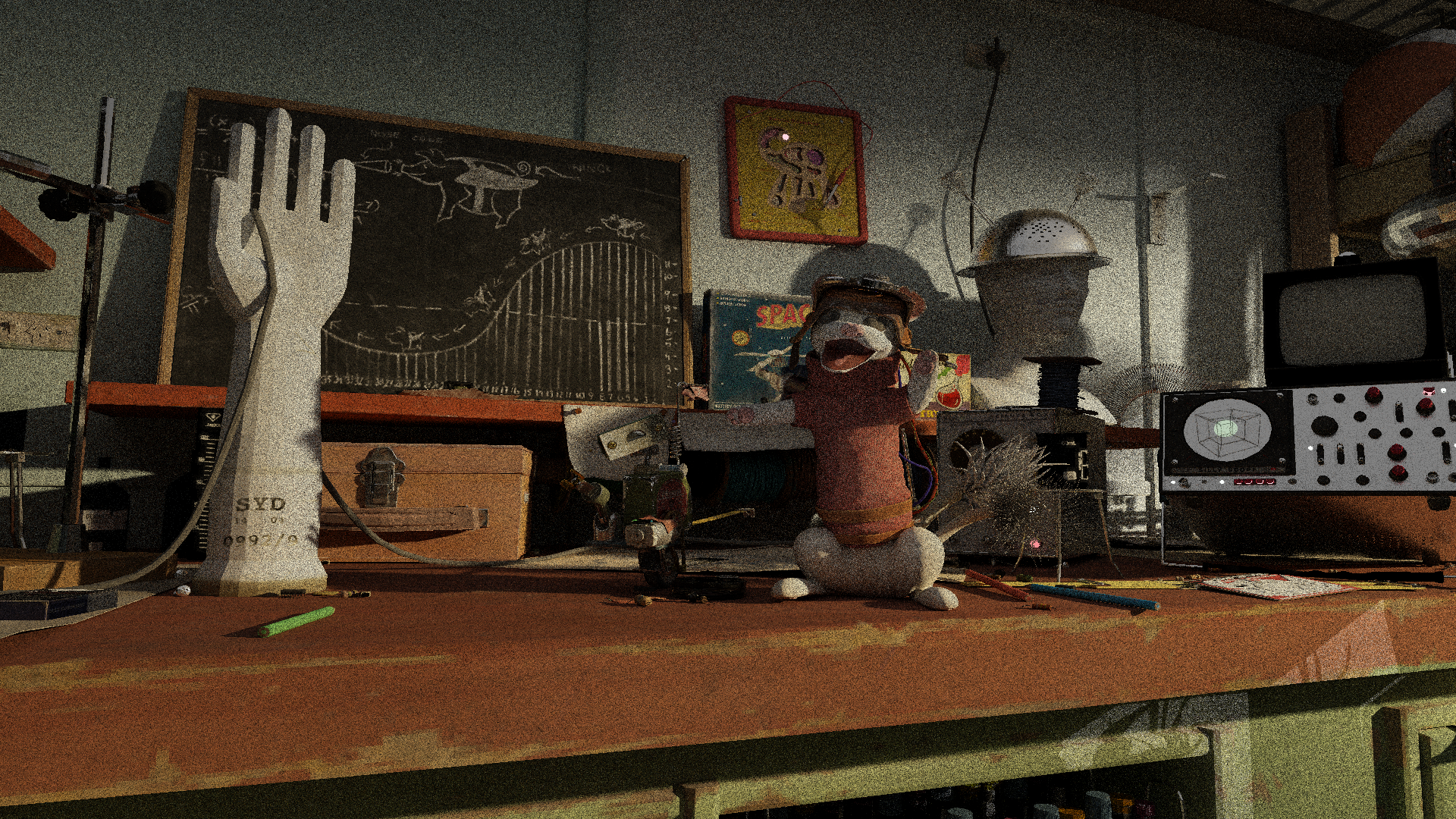
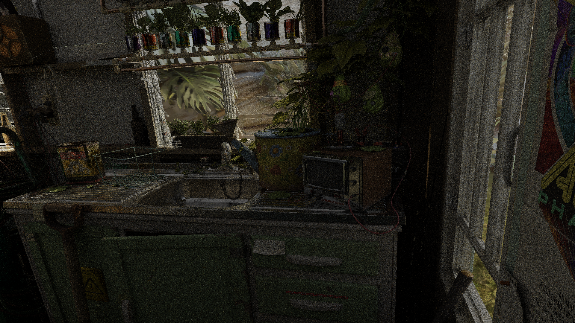
]]>Recently released hardware ray tracing extensions have made it feasible to render massive scenes containing billions of triangles on consumer grade GPUs. These extensions (AMD DGF and NVIDIA RTX Mega Geometry) operate on clusters of triangles, which are essentially small subsets of larger triangle meshes. If the triangles in these clusters have good spatial locality, it is possible to reduce the memory footprint of the ray tracing acceleration structures, as well as speed up build times. The video above showcases interactive rendering of the Moana island scene on an RTX 4070 Laptop GPU, which only has 8 GB of VRAM. This scene is notorious for its massive size, containing over 30 million instances and billions of instanced triangles. This series of blog posts will primarily focus on the techniques used to enable rendering this scene with only 8 GB of VRAM, using Vulkan.
Before any compression, a triangle mesh is first separated into multiple triangle clusters, with a maximum of 128 triangles per cluster. There are several ways to create these clusters, such as by partioning based on the surface area heuristic (SAH) or graph partitioning on shared edges (what Nanite does). For those unaware, SAH partioning greedily groups triangles such that the surface area of the group’s bounding box is minimized. Graph partioning groups graph nodes such that the sum of the weights of external edges (i.e pointing to nodes outside the group) are minimized. In this case, a node represents a triangle, and an edge represents the number of edges a triangle shares with another triangle. I chose to use graph partioning for clusterization because it minimizes the number of duplicated vertices across all clusters, which reduces the total geometry memory footprint as much as possible. While this may produce clusters that are slower to ray trace at runtime, conserving memory is necessary due to our limited budget.
All unique geometry is stored according to the AMD Dense Geometry Format (DGF), except clusters are not limited to 128 bytes. This format stores all vertex positions and attributes as variable bit width
offsets from an anchor value, saving memory. Also, instead of storing three indices per triangle, the format uses generalized triangle strips, which use a 2-bit control field per triangle to indicate how each
triangle k is generated.
RESTART(0) : Consume 3 indices and restart strip
EDGE1(1) : Consume 1 index and re-use edge 1 of triangle i - 1
EDGE2(2): Consume 1 index and re-use edge 2 of triangle i - 1
BACKTRACK(3) : Consume 1 index and re-use the remaining edge of triangle i - 2

// The first triangle in a triangle strip is always a RESTART, and BACKTRACK is only allowed if the previous triangle was EDGE1 or EDGE2.
Listing 1. Generalized triangle strip control types
While generalized triangle strips reduce the memory needed to encode the topology of a triangle mesh, it is no longer trivial to calculate the vertex indices used by a particular triangle.
Decoding the necessary data from this format can be slow, leading to noticeable performance degradation. In the DGF paper, the authors report a
reduction in performance by up to a factor of 2.3x compared to uncompressed base geometry.
This slowness is due to an O(N) decoding algorithm that calculates the vertex indices of a triangle in a triangle strip, listed below.
Unfortunately, to decode a triangle k, this algorithm requires scanning all k preceding triangles in the strip, which is slow and leads to poor execution coherence on GPUs.
In the worst case, a single thread in a warp could be scanning the end of a triangle strip, stalling all other completed threads.
// r represents the number of triangle restarts that have occurred
// index is the triangle index
r ← 1
for k = 1 -> index do
    ctrl <- Control[k]
    prev <- indexAddress
    if ctrl = RESTART then
        r <- r + 1
        indexAddress <- [2r + k - 2, 2r + k - 1, 2r + k]
    else if ctrl = EDGE1 then
        indexAddress <- [prev[2], prev[1], 2r + k]
        bt <- prev[0]
    else if ctrl = EDGE2 then
        indexAddress <- [prev[0], prev[2], 2r + k]
        bt <- prev[1]
    else if ctrl = BACKTRACK then
        if prevCtrl = EDGE1 then
            indexAddress <- [bt, prev[0], 2r + k]
        else
            indexAddress <- [prev[1], bt, 2r + k]
        end if
    end if
    prevCtrl <- ctrl
end for
Listing 2. GTS O(N) decoding algorithm
To improve decoding performance, I’ve implemented an O(1) algorithm that uses bit intrinsics instead of linearly scanning each control bit.
The key insight is that it’s possible to find the values of prev[0], prev[1], and prev[2] backwards from a selected triangle k.
First, instead of using a 2-bit control field per triangle, we’ll now use 3 1-bit control fields: one each for RESTART, BACKTRACK, and
EDGE1. Decoding the control type for each triangle is self-explanatory except for two cases. If none of the bit fields are set, the triangle has control type EDGE2.
If the BACKTRACK control bit is set, the corresponding bit in the EDGE1 field denotes what edge is used from triangle k - 2.
So if the ctrl for k - 1 was EDGE2, then the EDGE1 bit field is set, and if it was EDGE2, the EDGE1 bit field is unset.
Converting the data to this format enables the use of popcount/countbits intrinsics to calculate the number of restarts that have occurred before k, meaning we no longer
have to manually check the ctrl bit of all triangles preceding k.
It also allows for the use of bit scan intrinsics, whose usage will be described shortly.
Notice that the last entry of indexAddress for all four control types is always 2r + k. Thus, any instance of prev[2]
is simply 2r + k - 1. We now need to determine what the values of prev[0] and prev[1] are.
Let’s temporarily assume that the ctrl for triangle k is EDGE1, and that the triangle strip contains no backtracking.
We can manually observe what the value of prev[1] is in the three remaining cases.
if prevCtrl = RESTART, 2r + k - 2
else if prevCtrl = EDGE1, prev[1] of triangle k - 1
else if prevCtrl = EDGE2, prev[2] of triangle k - 1
Listing 3. Potential values of prev[1]
We know what the values of prev[2] and 2r + k - 2 are, meaning that if the previous ctrl bit is either a RESTART or EDGE2, we’re able to decode the value of prev[1].
If the previous ctrl is unfortunately an EDGE1, then we have to repeatedly check the preceding ctrl bits until we find a RESTART or EDGE2.
The following pseudocode illustrates the decoding algorithm.
for k = index - 1 -> 0 do
    ctrl <- Control[k]
    if ctrl = RESTART, return 2r + k - 1
    else if ctrl = EDGE1, continue
    else if ctrl = EDGE2, return 2r + k - 1
Listing 4. Decoding pseudocode when ctrl is EDGE1
The above process can be repeated for EDGE2. Now, the loop continues when ctrl = EDGE2, and ends only when RESTART or EDGE1 are found.
for k = index - 1 -> 0 do
    ctrl <- Control[k]
    if ctrl = RESTART, return 2r + k - 2
    else if ctrl = EDGE2, continue
    else if ctrl = EDGE1, return 2r + k - 1
Listing 5. Decoding pseudocode when ctrl is EDGE2
What happens when we add backtracking? Recall that backtracking reuses the remaining edge of triangle k - 2.
Let’s revisit the ctrl = EDGE1 case.
// ...
else if ctrl = BACKTRACK then
    if prevCtrl = EDGE1 then
        return prev[0]
    else return bt
Listing 6. Backtracking
If prevCtrl is EDGE1, we need to find the value of prev[0]. Since indexAddress[0] = prev[2] when ctrl is EDGE1,
this value can be determined. If prevCtrl is EDGE2, then we need to find the value of bt, which unfortunately is also prev[1]. This means
to calculate the value of prev[1], we need to find the most recent triangle with control types
RESTART, EDGE2, or EDGE1 with a succeeding BACKTRACK.
Following a similar process when ctrl EDGE2,
we now need to find the most recent triangle that is either
a RESTART, EDGE1, or EDGE2 immediately followed by BACKTRACK. The pseudocode for these two cases are listed below.
for k = index - 1 -> 0 do
    ctrl <- Control[k]
    wasBt <- bt
    bt <- false
    if ctrl = RESTART, return 2r + k - 1
    else if ctrl = EDGE1 or wasBt, continue
    else if ctrl = EDGE2, return 2r + k - 1
    else if ctrl = BACKTRACK
        bt <- true
        prevCtrl <- Control[k - 1]
        if prevCtrl = EDGE1, return 2r + k - 2
        else if prevCtrl = EDGE2, continue
Listing 7. Decoding pseudocode for EDGE1
for k = index - 1 -> 0 do
    ctrl <- Control[k]
    wasBt <- bt
    bt <- false
    if ctrl = RESTART, return 2r + k - 2
    else if ctrl = EDGE2 or wasBt, continue
    else if ctrl = EDGE1, return 2r + k - 1
    else if ctrl = BACKTRACK
        bt <- true
        prevCtrl <- Control[k - 1]
        if prevCtrl = EDGE2, return 2r + k - 2
        else if prevCtrl = EDGE1, continue
Listing 8. Decoding pseudocode for EDGE2
The above loops can be represented as bit scan operations. We use firstbithigh to find the most significant bit of the EDGE1 and RESTART bitmasks that is less than
the current triangle’s bit. If EDGE2 is needed, we bitwise invert the EDGE1 mask, and clear any bits where RESTART or BACKTRACK are set.
Below is HLSL code that decodes the values of indexAddress for a given triangleIndex.
int3 indexAddress = int3(0, 1, 2);

uint dwordIndex = triangleIndex >> 5;
uint bitIndex = triangleIndex & 31u;

uint bit = (1u << bitIndex);
uint mask = (1u << bitIndex) - 1u;

uint3 stripBitmasks; // contains the aforementioned RESTART, EDGE1, and BACKTRACK bitmasks for a group of 32 triangles
uint isRestart = BitFieldExtractU32(stripBitmasks[0], 1, bitIndex);
uint isEdge1 = BitFieldExtractU32(stripBitmasks[1], 1, bitIndex);
uint isBacktrack = BitFieldExtractU32(stripBitmasks[2], 1, bitIndex);

uint restartBitmask = stripBitmasks[0];
uint edgeBitmask = stripBitmasks[1];
uint backtrackBitmask = stripBitmasks[2] & mask;

uint isEdge1Bitmask = 0u - isEdge1; // wraps to 0xffffffff when isEdge1 is 1

uint prevRestartsBeforeDwords = dwordIndex ? numPrevRestartsBeforeDwords[dwordIndex - 1] : 0u;
uint r = countbits(restartBitmask & mask) + prevRestartsBeforeDwords;

if (isRestart)
{
    r++;
    indexAddress = uint3(2 * r + triangleIndex - 2, 2 * r + triangleIndex - 1, 2 * r + triangleIndex);
}
else
{
    indexAddress.z = 2 * r + triangleIndex;
    mask >>= isBacktrack;
    indexAddress.y = 2 * r + triangleIndex - 1 - isBacktrack;

    int restartHighBit = firstbithigh(restartBitmask & mask);
    int otherEdgeHighBit = firstbithigh(~restartBitmask & ~backtrackBitmask & ((isEdge1Bitmask ^ ((backtrackBitmask >> 1) ^ edgeBitmask)) & mask));

    int prevRestartTriangle = restartHighBit == -1 ? (dwordIndex ? prevHighRestartBeforeDwords[dwordIndex - 1] : 0u) : restartHighBit + dwordIndex * 32;

    int3 prevHighEdge = isEdge1 ? prevHighEdge2BeforeDwords : prevHighEdge1BeforeDwords;
    int prevOtherEdgeTriangle = otherEdgeHighBit == -1 ? (dwordIndex ? prevHighEdge[dwordIndex - 1] : -1) : otherEdgeHighBit + dwordIndex * 32;

    int prevTriangle = max(prevRestartTriangle, prevOtherEdgeTriangle);
    uint isEdge1Restart = isEdge1 && (prevRestartTriangle == prevTriangle);

    uint increment = (prevOtherEdgeTriangle == prevTriangle || isEdge1Restart);
    indexAddress.x = 2 * r + prevTriangle - 2 + increment;

    indexAddress = isEdge1 ? indexAddress.yxz : indexAddress;
}
Listing 9. O(1) decoding code
In this implementation, each cluster header now requires 12 extra bytes to cache the most recent occurrence of each triangle type for each group of 32 triangles, as well as the number of restarts. If the requisite triangle types are not found in the triangle’s group of 32, this cached value is used. While this caching is not strictly necessary, it simplifies the runtime logic, and the extra memory cost is negligible.
AMD recently published an alternative O(1) decoding algorithm, which can be found here.
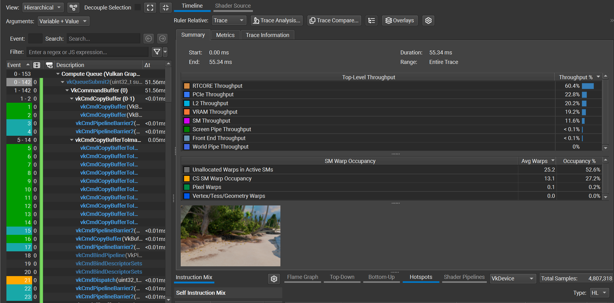 Figure 1. Nsight capture for shotCam, using O(1) decoding
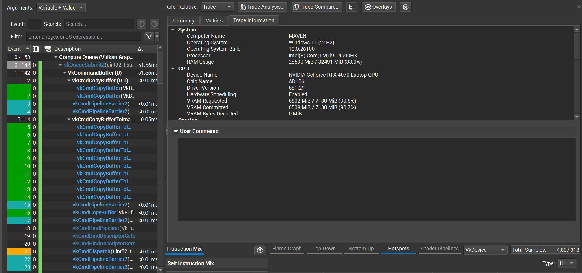 Figure 2. Nsight trace info
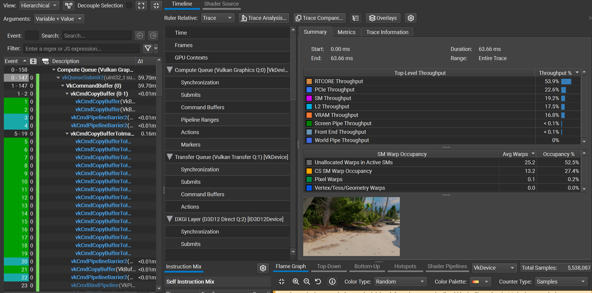 Figure 3. Nsight capture for shotCam, using O(N) decoding
Using the shotCam camera, the total frame time is 51.56 ms using the O(1) decoding method, and 59.70 ms using the O(N) decoding method. The O(1) decoding algorithm saves about 8 ms per frame, which is a ~1.16x speedup. All images are rendered using a basic megakernel unidirectional path tracer with 3 bounces and next event estimation, at a resolution of 2560x1440.
In the next few posts I’ll discuss how I used the RTX Mega Geometry extensions to reduce BVH memory costs, as well as how textures are streamed in my renderer.
Barczak et. al. 2024, “DGF: A Dense, Hardware-Friendly Geometry Format for Lossily Compressing Meshlets with Arbitrary Topologies” https://gpuopen.com/download/DGF.pdf
Disney 2018, “Moana Island data set” https://www.disneyanimation.com/data-sets/
Meyer et. al. 2025 “Parallel Dense-Geometry-Format Topology Decompression” https://doi.org/10.2312/egs.20251050
]]>